
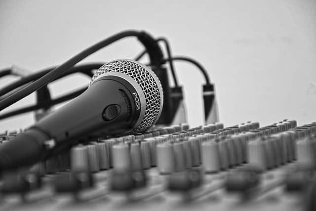
Adjustment of the optimal timbre of the vocals
Whether it's a human voice, a song, or the sound of an instrument, it's not a single tone, b...
Read moreWhen designing and installing an audio system, it is inevitable to encounter the problem of mating between the amplifier and the speaker. From an artistic point of view, the meating of the amplifier and the speaker should be suitable for cool and warm, soft and hard in terms of timbre, and finally make the whole set of equipment restore the tone neutral. From a technical point of view, the amplifier and speaker are matched with the following points: power matching; Power reserve matching; impedance matching; Matching the damping factor. If we recognize the above four points when mating, the performance of the equipment used can be fully utilized.
1. Power matching: To meet the requirements of high-fidelity listening, the rated power should be determined based on the optimal listening sound pressure. We all have this feeling: when the volume is low, the sound is weak, thin, and the dynamics cannot come out, the gloss, the low frequency is significantly lacking, the fullness is poor, and the sound seems to be shrunk inside and cannot come out. When the volume is right, the sound is natural, clear, round, soft, full, powerful, and dynamic. However, when the volume is too high, the sound is stiff, not soft, rough, and has a feeling of rooting in the ears. Therefore, the reproduction sound pressure level has a great relationship with the sound quality, and the sound pressure level of the listening area is best 80~85dB (A-weighted), and we can calculate the rated power of the speaker and the rated power of the amplifier from the distance from the listening area to the speaker and the characteristic sensitivity of the speaker.
2. Power reserve matching: Speaker: In order to withstand the impact of sudden strong pulses in the program signal without damage or distortion. Here's an empirical value: the nominal power rating of the selected speaker should be 3 times the theoretically calculated power.
Amplifier: Compared with tube amplifiers and transistor amplifiers, the required regular reserves are different. This is because tube amplifiers have a gentler overload curve. For overloaded music signal peaks, tube amplifiers do not obviously produce clipping, but only round the tip of the peak. This is what we often call flexible peak shearing. After the transistor power is placed at the overload point, the nonlinear distortion increases rapidly, causing severe clipping to the signal, and it does not round the peak but flattens it neatly. Some people use a composite impedance analog speaker composed of resistors, inductors, and capacitors to test the actual output capabilities of several high-quality transistor amplifiers. The results show that in the case of phase shift of load, there is an amplifier with a nominal 100W, and the actual output power is only 5W when the distortion is 1%! Therefore, the selection of the reserve of the transistor amplifier:
Hi-Fi amplifier: 10x
Civil high-end amplifier: 6~7 times
Civil mid-range amplifier: 3~4 times
Tube amplifiers, on the other hand, can be larger or smaller than the above ratio.
The amount of margin left for the average sound pressure level and the maximum sound pressure level of the system should depend on the content of the broadcast program and the working environment. This redundancy is at least 10dB, and for modern pop music, jumping and other music, it is necessary to leave 20~25dB redundancy, so that the sound system can work safely and stably.
3. Impedance matching: It refers to the rated output impedance of the amplifier, which should be consistent with the rated impedance of the speaker. If the rated impedance of the speaker is greater than the rated output impedance of the amplifier, the actual output power of the amplifier will be less than the rated output power. If the rated impedance of the speaker is less than the rated output impedance of the amplifier, the audio system can work, but the amplifier is in danger of overloading, and the amplifier is required to have perfect overcurrent protection measures to solve it.
4. Matching of damping coefficient: The damping coefficient KD is defined as: KD = amplifier rated output impedance (equal to the rated impedance of the speaker) / amplifier output internal resistance. Since the internal resistance of the amplifier output has actually become the electrical resistance device of the speaker, the KD value determines the amount of electrical resistance that the speaker is subjected to. Of course, the KD value of the amplifier is not the larger the better, too much KD value will make the speaker impedance too heavy, so that the pulse front establishment time will increase, and the transient response index will be reduced. Therefore, when choosing an amplifier, you should not unilaterally pursue a large KD value. As a household high-fidelity amplifier damping coefficient has an empirical value for reference, the minimum requirements: transistor amplifier KD value greater than or equal to 40, tube amplifier KD value greater than or equal to 6.
To ensure the basic conditions for good steady-state characteristics and transient characteristics of the amplifier, attention should be paid to the cooperation between the isodynamic quality factor (Qm) and the amplifier damping coefficient (KD) of the speaker. This combination needs to be considered as part of the overall sound system of the speaker. The feeder equivalent resistance of the speaker should be small enough to be negligible compared to the rated impedance of the speaker. In fact, the power loss of the speaker feeder should be less than 0.5dB (about 12%) to achieve this fit.
Whether it's a human voice, a song, or the sound of an instrument, it's not a single tone, b...
Read more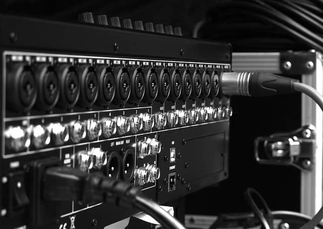
When designing and installing an audio system, the matching of amplifiers and speakers is an...
Read more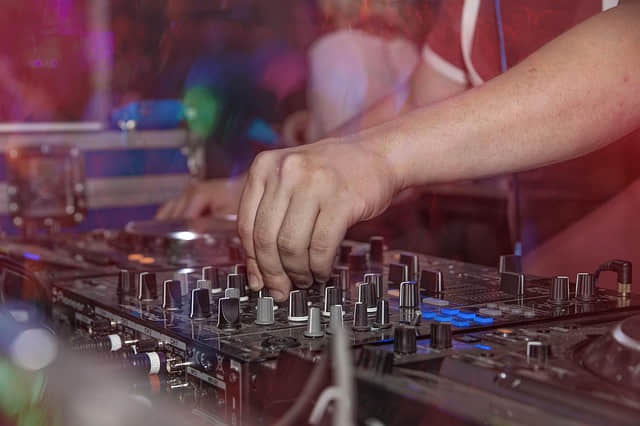
Club equalizers typically require a pink noise generator and a real-time spectrum analyzer f...
Read more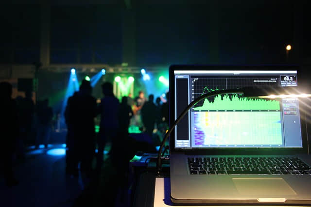
Currently, most professional sound systems used in domestic dance halls are imported equipme...
Read more
1. Hip-hop originated from Black culture. It's a laid-back and elegant form of music, named ...
Read more
As the year draws to a close, China's consumer goods export market, which should be bustling...
Read more